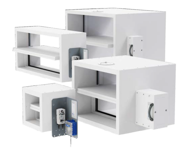
EK-JZ smoke control dampers with ventilation function for heat and smoke extraction

Conforms to VDI 6022
Classification
Nominal sizes
Nominal size B × H (in 5 mm increments):
Total lengths L [mm], without inspection cover:
Total lengths L [mm], optionally with inspection cover:
Special lengths L [mm], optionally with inspection cover:
Optional products
TROXNETCOM
All smoke exhaust fans are tested according to DIN EN 12101-3, for F200/F300/F400 and F600, depending on the type. CE marking and Declaration of Performance are provided. Speed adjustment for smoke exhaust fans
DIN EN 1751: Ventilation for buildings – Air terminal devices
Smoke control dampers are used in mechanical smoke extract systems. They are used for extracting flue gases and for providing additional supply air to single or multiple fire compartments. In the event of an incident, the smoke control dampers are opened or closed manually or automatically by an actuator. The actuator can be encased or not encased. The trigger signal is given either by a smoke detection device (e.g. duct smoke detector) or by a fire alarm system. Smoke control dampers have two safety positions: fully open and fully closed. In the case of fire-resistant smoke control dampers for multiple compartments, the safety position is either 'open' or 'closed', depending on the fire site and the path of the smoke to be extracted. If the position is 'open', the free cross-sectional area must be maintained even in the event of a fire. EK2-EU moves to the desired safety position after an automatic or manual control signal. A change in position is possible up to 25 minutes at a temperature load in accordance with the ISO standard fire curve (MA, manual activation). Position changes are also possible for modulation applications (Cmod) and thus pneumatic adjustment by approaching intermediate positions of the damper blade. Regular maintenance of the smoke control damper is necessary to ensure the required function.
Nominal sizes B × H | 200 × 200 mm – 1500 × 800 mm |
Volume flow range | up to 12000 l/s or 43200 m³/h |
Differential pressure range | Pressure level 3: -1500 – 500 Pa |
Operating temperature | -30 – 50 °C without temperatures below the dew point |
Upstream velocity* | ≤ 10 m/s with maximum dimensions > 10 – 15 m/s with reduced dimensions, up to a maximum of 43200 m³/h |
Leakage airflow when the damper blade is closed | DIN EN 1751, at least class 3 |
Casing air leakage | DIN EN 1751, class C |
EC conformity | EU Construction Products Regulation no. 305/2011 DIN EN 12101-8 Smoke and heat control systems – Smoke control dampers DIN EN 1366-10 Fire resistance tests for service installations – Smoke control dampers DIN EN 1366-2 Fire resistance tests for service installations – Fire dampers DIN EN 13501-4 Fire classification of construction products and building elements DIN EN 1751: Ventilation for buildings – Air terminal devices |
Declaration of Performance | DoP/EK2-EU/001 |
* If actuation (change of damper blade position, leaving the end position) is safely prevented with an upstream velocity of more than 10 m/s, the smoke control damper can be used up to its maximum dimension with an upstream velocity of 15 m/s.
This specification text describes the general characteristics of the product. Texts for variants can be generated with our Easy Product Finder design programme.
A life cycle assessment is available for the product type in form of an Environmental Product Declaration (EPD) that has been checked and published by an EPD programme operator.
Smoke control dampers in accordance with product standard DIN EN 12101-8, tested according to DIN EN 1366-10 and DIN EN 1366-2, in square or rectangular design for use in smoke extract systems. Smoke control dampers are used to prevent the transfer of smoke and combustion products from a fire area. In addition, smoke control dampers prevent the escape of released, hazardous and toxic extinguishing gases from the affected area and control pressure ventilation and venting devices in pressurisation systems. The EK2-EU is suitable as a pressure relief damper for gas extinguishing systems. For extracting smoke gases and for providing additional supply air to single or multiple fire compartments. The EK2-EU can be used in smoke extract systems that have been approved for ventilation. The fireresistant smoke control damper for multiple compartments is suitable for installation in solid walls and shafts, lightweight partition walls and ceilings, as well as in and on fire-resistant smoke extract ducts. Open-Close actuator, optionally with fully wired and ready-to-operate bus control module inside the temperature-resistant actuator encasing.
Equivalence criteriaMaterial and surfaces
| EK2-EU | – | MA | – | IC | – | C1 | / | DE | / | 1500 × 800 × 950 | / | 03 | / | Q0 | / | B24 | / | P1 - RAL 9010 |
| | | | | | | | | | | | | | | | | | | | | |||||||||
| 1 | 2 | 3 | 4 | 5 | 6 | 7 | 8 | 9 | 10 | |||||||||
| Type | EK2-EU Smoke control damper |
| Construction | manual override (thermally encased actuator) |
| Inspection cover | With 2 inspection covers |
| Coating | Promat impregnation (on calcium silicate surfaces) |
| Country of destination | Germany |
| Nominal size [mm] | Width 1500, height 800, length 950 |
| Accessories | Fixing tabs and high-temperature sealing tape (HT) |
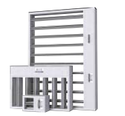
| Attachment 1 | Operating side: Perforated metal plate, Installation side: Side without attachment |
| Attachment 2 | Actuator 24 V AC/DC with TROXNETCOM AS-EM/EK |
| Surface of attachment 1 | Powder-coated, RAL 9010 (pure white), GU 50 |
Compartir la página
Recomendar la página
La página puede ser recomendada compartiendo este enlace.
Contacto
¡Gracias por su mensaje!
Su recomendación ha sido remitida con éxito.
Contacto
Estamos aquí para ayudarle

Please specify your message and type of request.
Tel.: +52 55 5271 2842
Contacto
¡Gracias por su mensaje!
Your message is send and will be processed shortly.
Our department for Service-Requests will contact you asap.
For general question regarding products or services you can also call:
Tel.: +52 55 5271 2842
Contacto
Estamos aquí para ayudarle
Please specify your message and type of request.
Tel.: +52 55 5271 2842
Contacto
¡Gracias por su mensaje!
Your message is send and will be processed shortly.
Our department for Service-Requests will contact you asap.
For general question regarding products or services you can also call:
Tel.: +52 55 5271 2842